blog 2 (gears)
Hi everyone! Welcome back to my blog. 😌😌
In today’s blog, I will describe:
1. The definition of gear module, pitch circular diameter and the relationship between gear module, pitch circular diameter and number of teeth.
2. The relationship between gear ratio (speed ratio) and output speed, between gear ratio and torque for a pair of gears.
3. How I can design a better hand-squeezed fan, including the sketches
4. How my practical team arranged the gears provided in the practical to raise the water bottle, consisting of:
a. Calculation of the gear ratio (speed ratio)
b. The photo of the actual gear layout.
c. Calculation of the number of revolutions required to rotate the crank handle.
d. The video of the turning of the gears to lift the water bottle.
5. My Learning reflection on the gears activities.
Without any further ado, let’s proceed to learn more about gears!
1. The definition of gear module, pitch circular diameter and the relationship between gear module, pitch circular diameter and number of teeth.
A gear is a rotating circular device that contains teeth, which can mesh with another toothed part to form a gear train that can transmit torque and speed.
A ‘gear module’ is defined to be is the unit of size that indicates how big or how small a gear is. The unit for the module is in millimetres (mm). The larger the module number, the larger the size of the teeth.

The pitch circular diameter (PCD), gear module and number of teeth are related through the following equation:
PCD = m x z
where ‘m’ refers to the gear module and ‘z’ refers to the number of teeth in a gear.
Now that we have learnt about this relationship, let us look at the relationship between gear ratio and output speed and torque of gears.
2. Below is the relationship between gear ratio (speed ratio) and output speed for a pair of gears.
‘Gear ratio’ is defined to be the number of rotations of driven gear to the number of rotations of a driver gear (output/input). Gear ratio is also the ratio of the number of teeth in the driven gear to the number of teeth in the driven gear.
Gear ratio = Z2/Z1,
where Z2 is the number of teeth in driven gear and Z1 is the number of teeth in the driver gear.
For speed ratio, it is the ratio of the input over the output.
When the gear ratio is greater than 1, the output speed will be lower. However, when the gear ratio is lesser than 1, the output speed will be greater.
Below is the relationship between gear ratio and torque for a pair of gears.
Torque is defined as the measure of twisting force, calculated as the product of circumferential force multiplied by the radius of the gear. This tells us that bigger gears will have more torque than smaller gears due to the larger radii of the gears.
Hence when the gear ratio is greater than 1, the torque is greater. However, when the gear ratio is lesser than 1, the torque is lower.
3. Below are the proposed design to make the hand-squeezed fan better:
4. Below are the description on how my practical team arranged the gears provided in the practical to raise the water bottle.
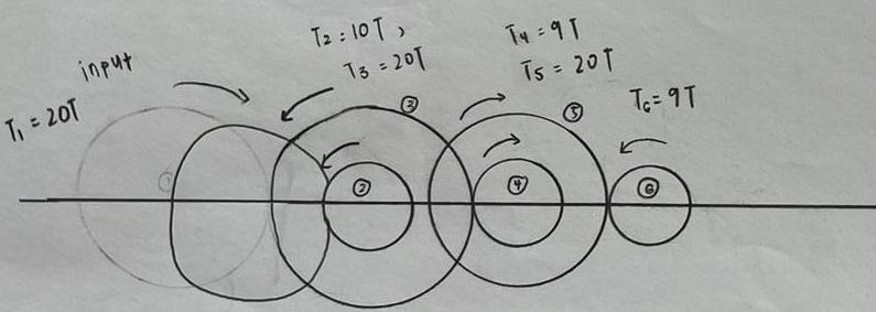
(a) Calculation of the gear ratio

Gear ratio = Z1/Z2 = 40/30 = 4/3
Gear ratio = 40/12 = 10/3
Hence, combined gear ratio = 4/3 x 10/3 = 40/9 = 4.44 (3s.f.)
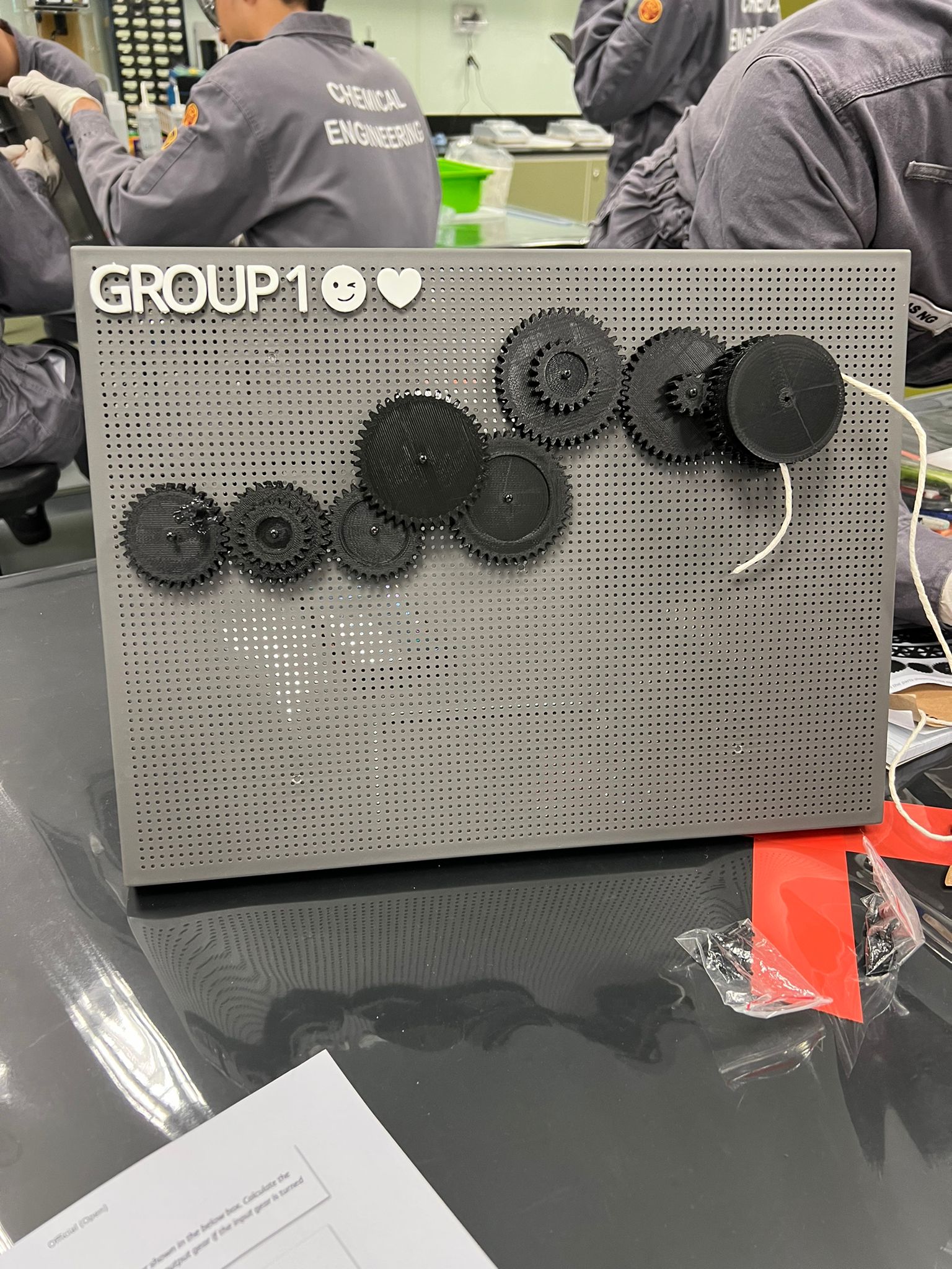
(b) The photo of the actual gear layout
(c) Calculation of the number of revolutions required to rotate the crank handle
Using the diagram shown in part (a) as the reference,
h = 200mm
1 rotation = πD
D = 22mm.
No. of rotations = 200/ πD = 2.9
gear ratio = input/output
4.44 = input/ 2.9
hence, input = 12.89 = 13 (rounded up to whole number)
(d) Video of turning the gears to lift the water bottle
5. Below is my Learning Reflection on the gears activities
Initially before carrying out this practical, my exposure to the uses of gears and their functionality was minimal. Of course I knew gears existed in bicycles and that there are many uses for gears in a chemical manufacturing industry. But I was not aware of the mechanism behind gears. Therefore, I felt that this practical was very enriching for me.
Before the practical, we were required to watch 4 videos on gears to prepare ourselves for the in-practical activities. Through this video, I got to learn more about different concepts like gear ratio, torque, compound and idler gears. Although these were new concepts, I felt that it was simple to understand! Moreover, these basic were SUPER USEFUL when we got to apply our knowledge in a practical setting. From the videos, I got to learn about the relationships between the gear ratio and output speed and torque. These concepts helped us carry out activity 1 and 2 during the practical session.
During practical 1, we were required to design a gear ratio to raise 600ml of water with minimal input force. Before we began assembling the most desirable gear sequence, we revisited the concept of gears. Since we wanted to lift a heavy bottle of water with minimal input, we used our understanding on the relationship between gear ratio and torque. To achieve the most optimum sequence, we had to carry out much trial and error as well as calculations. After having a rough idea on how we should place our gears, we began to assemble it. We faced some challenges initially as the pins would not go through the grey board and thus we had to position our gear sequence strategically, in order for it to work. Although we had planned to execute out initial idea, we met some hiccups along the way because when certain gears were placed together, the gear handle could not turn properly. Hence we had to keep modifying our idea to create our most suitable sequence. This encouraged us to use our critical thinking and problem solving skills! In the end, we managed to construct a sequence that could be turned with minimal friction. We concluded that our set up was successful since we could lift up the 600ml of water above 20cm! Since we distributed the workload evenly among our group members, we even managed to finish our activity earlier than we had planned to. Hence this activity taught me about the importance of teamwork, innovative thinking and knowledge application.
During activity 2, we were required to assemble a hand powered fan. Similarly to activity 1, before we made any progress with the assembling part, we made it a priority to fully understand the activity requirements first. Since this activity involved a fan, we decided that the output speed has to be high in order for the product function to be fulfilled. Therefore the gear ratio has to be lesser than 1, so that the output speed is high. Again through doing some preparation work (calculations, initial sketch), we were able to have a vision of how our final set up should look like. A challenge we faced during this challenge was that the gears were slightly more fragile since they were smaller in size. Hence we had to make sure we would not break any teeth of the gears when we were setting up the fan.
Overall, this practical was very educational as I got to apply my theory knowledge in a practical situation. One important thing I learnt this practical was that theoretical values may not necessarily be the same as actual values. For both our activities, the theoretical values were not our actual values. Although they were close to each other, this also tells us that we have to be aware of causes that may result in this inaccuracy (eg. frictional loss of energy).
I hope to apply the knowledge accumulated from this practical, into my future endeavours! With that, here are some pictures from our practical session! 😋


Comments
Post a Comment